Residental Booster Pump (RP3)
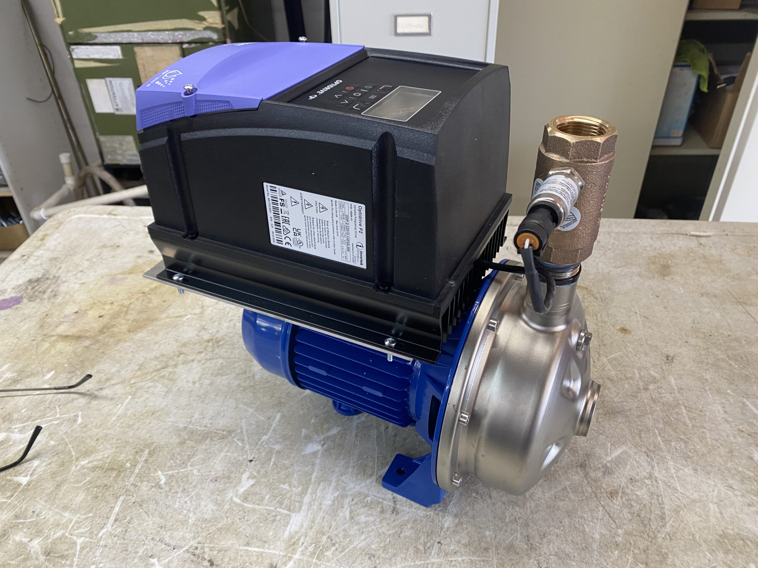
The Residential Perfect Pressure Pump (RP3) Is our newest offering that reduces cost but enjoys all the algorithms of our commercial P3. It also carries the same 3 year warranty. It is rugged implementing a NEMA 4X, water proof drive, stainless steel pump , impeller and brass check valve.
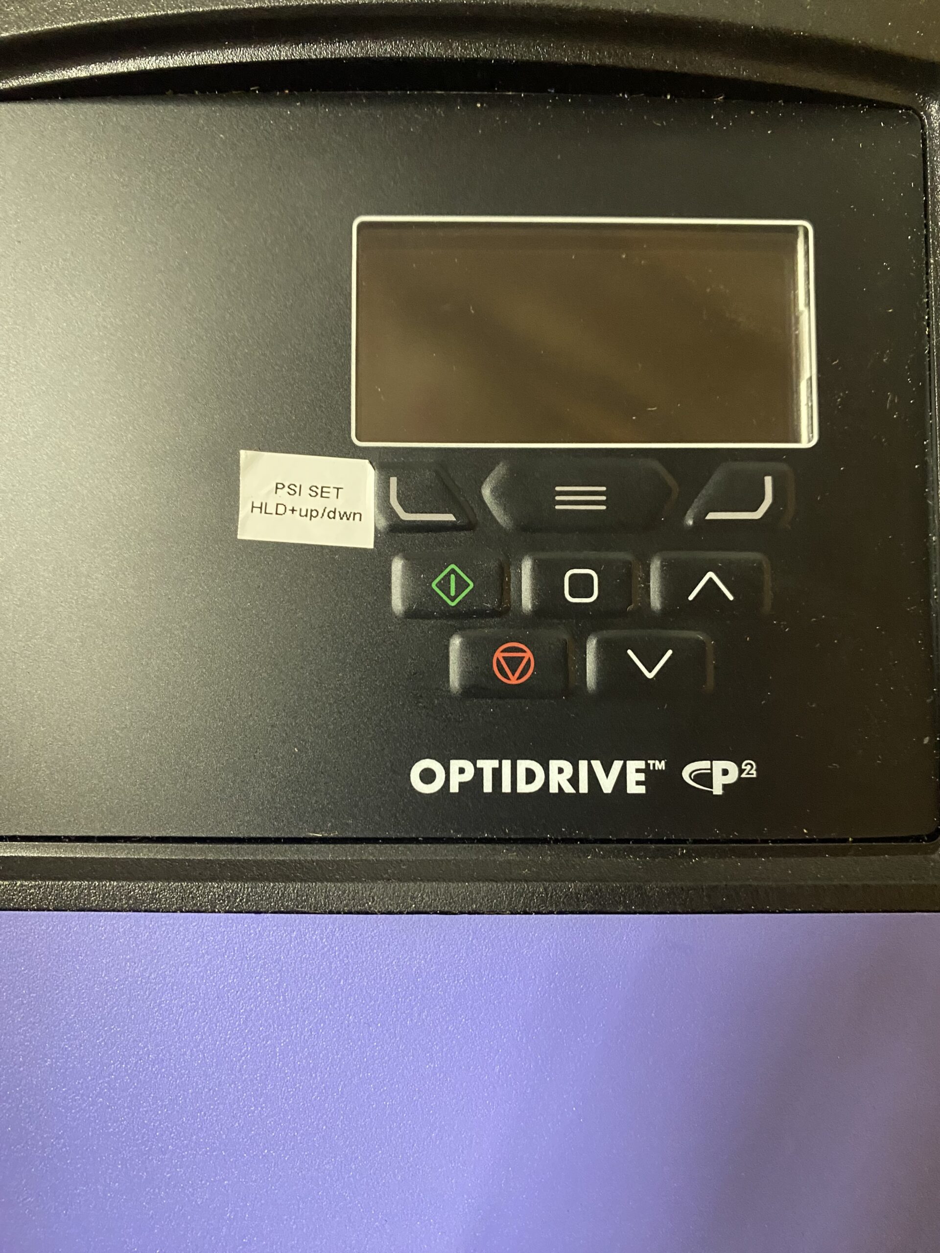
The RPS does not carry NSF certification and is designed for residential applications. Unlike our commercial P3, it does not have an output gauge, disconnect switch, On/ off switch or pressure knob. Pressure is set on the key pad along with start/stop functions.
This unit can be sold direct to consumers if you live in an area with no rep. Direct pricing is $2,900.00. Multiple unit pricing is available along with rep pricing if you purchase 5 or more units. Terms are CIA. Call TAW for more information. (407) 493.2355
This unit is 15 lbs. lighter than our commercial P3 allowing it to be shipped Fed-X. Shipping weight is 41 lbs. Box dims are 20″L X 14″H X 13″W.
Once you confirm there is no damage, please take the time to read the Installation and operation manual on this site.
Included in the box:
- Pump, complete with motor & drive, bronze check valve & pressure transducer.
- When mounting the pump try and make your install as easy as possible.
Determine a location near the water coming into the home and as convenient as possible to power. You will need 230V power or you can purchase an optional 110V to 220V step up transformer if you do not have 220V power. Most homes built in America have 220V available. - Mount the pump above grade by at least 2 inches if being mounted outdoors. The reason for this is to prevent water puddling at the base of the pump. Although the pump is water proof it is NOT submersible. Standing water will damage the unit and void the warranty. A quick method of mounting is to bury a cement cinder block 3/4 in the ground on its side. Then position the pump on top of the block and mark the hole pattern with a sharpie.
- Purchase a tapcon kit 1.5″ X 1/4″ is sufficient, the kit comes with a mason drill.
- Remove the pump temporarily.
- Pre-drill the holes you previously marked.
- Re-place the pump on the block aligning the holes.
- Screw down the tap-cons until snug.
Depending on local codes, you may have PVC, CPVC, copper, stainless or galvanized pipe.
Please follow local codes before installing the pump with proper material.
At this point, it may be a good idea to hire a plumber since this is an advanced DIYer project. But if you feel qualified and are up to the challenge, let’s continue.
- Turn off the main water supply. If you are on city water, it’s typically on your property close to the street.
- Once you are certain the water is turned off by opening a hose bib and allowing any retaining water to bleed off, cut into the line at a place convenient to the pumps locale.
- This is where your location will change the type of pipe you will use.
- We suggest always installing a bypass valve arrangement. It will require 3 valves and 2 quick disconnect fittings.
- Thread the 1 1/4″ pipe or combination of reducer and your pipe to the inlet side of the pump, also called the suction side.
- Thread the 1″ NPT outlet side of the pump using appropriate materials and reducers if needed to match your existing piping.
- The bypass valve arrangement is shown in the diagram to the right.
- Once the plumbing is finished, apply water by turning on the house water supply and slowly turning on the input and output valves. Turn OFF the bypass valve and check for leaks. Fix any leaks.
- Check the water inlet pressure gauge that you mounted to your existing pipes.
- Check output pressure gauge supplied on the pump.
- The pump is now ready for power.
- If you are not qualified to wire this product, please contact a certified electrician. Please adhere to local codes when wiring this product.
- A 2 pole, 15 amp GFCI breaker is required to protect personnel and product.
- Wire the pump with no less than 14 gauge two wire with a ground of equal gauge.
- Use mechanical reliefs and mechanical shielded cable.
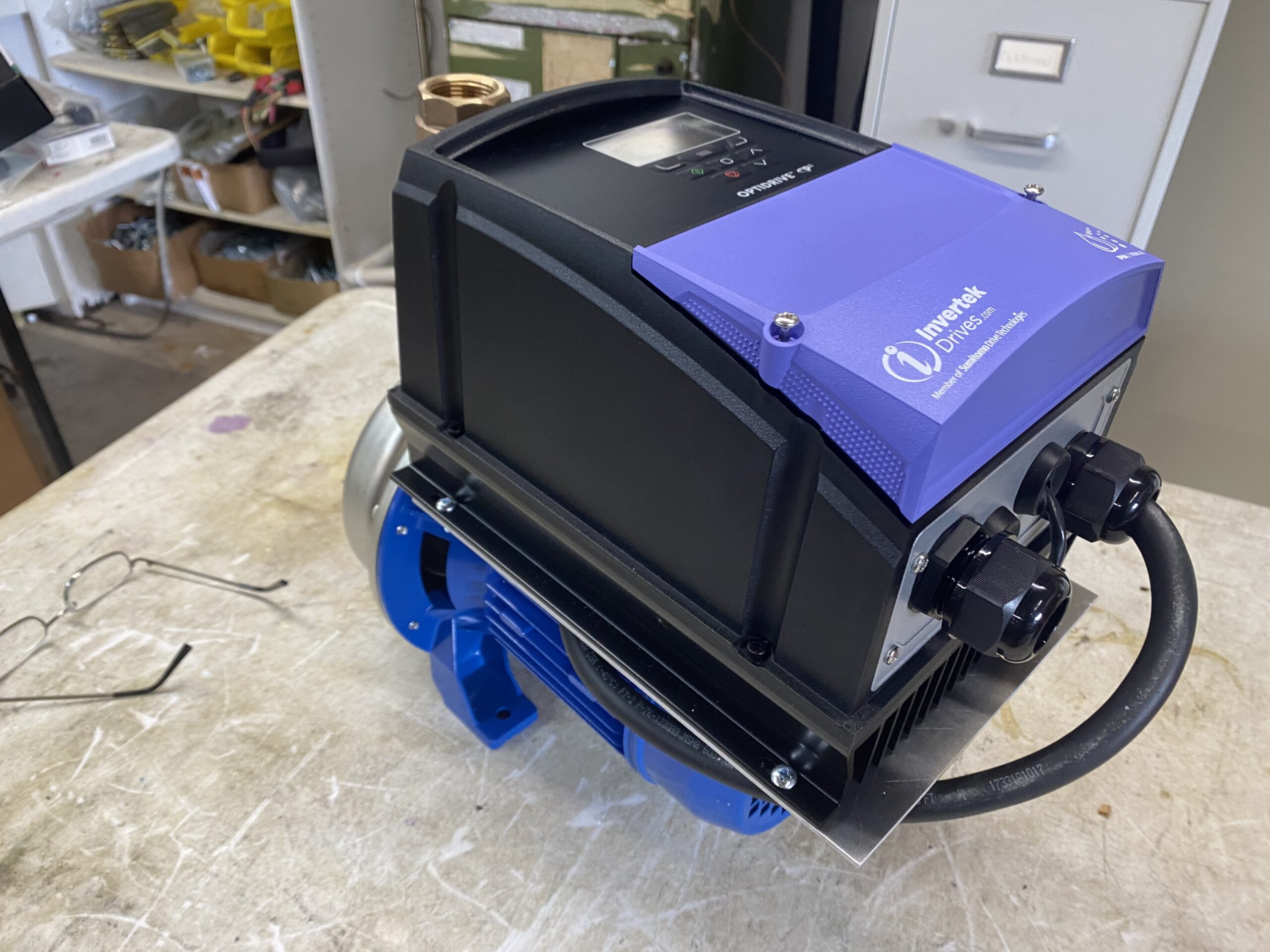
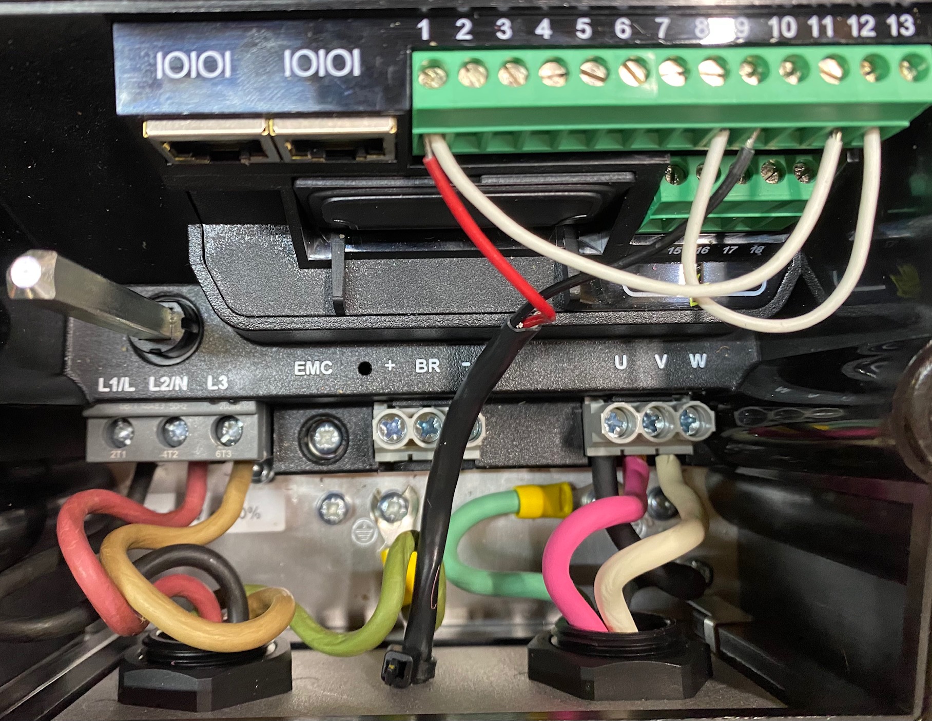
- Open up the cover of the drive and feed the cable through the strain relief hole on the right looking at the back of the unit.
- Connections inside the drive are made by stripping back THNN wire by at lease 1/2″ and pushing the wire into the holes as shown in the picture to the right. Make certain the ground is connected. Connect to L1 & L2 as shown in the right picture. Ground is connected under screw attached to the heatsink.
- Tug on the wires to insure good connection and once you are confident they are connected replace the cover BEFORE applying power.
- With the cover on the unit, apply power to the unit. The unit is rated 230v sngle phase, 15 amp2 pole GFI breaker should be used.
- Display will light and show actual pressure & setpoint pressure alternating every 2 minutes.
House pressure should not be set above 75 PSI and the pump limits this setting to 80. We advise keeping the pressure between 60- 65PSI . Make note of the incoming pressure. With the pump off and turning on a faucet the display will show you the normal house pressure without the pump. The pump can not supply more than 40PSI above your incoming pressure, attempting to do this will make the pump cavitate and over a long period of time could damage the pump. The pump will show cavitation pressure if you are attempting to overload the pump. It will slow the pump down until the pressure can be maintained. Air in the line will be indicated by “water problem” displayed. If this occurs, bleed the pump from air by loosening the 12 o’clock position hex nut on the pump 1/2 turn CCW. Water and air will escape so have a towel handy. Once all the air bubbles stop and only water is coming out the pump is ready to run. To prevent this damage, the pump incorporates an anti-cavitation algorithm. If the pump is running at full speed but can not maintain the pressure set point, it will automatically lower the pressure setpoint to the point it can keep up. determine your maximum flow by turning on several fixtures and a shower & observe the incoming pressure, the setpoint should not be set higher than 40PSI above this to prevent the cavitation algorithm from ever operating. For example, if you turn on two showers and a faucet and your supply pressure is 10 PSI, the pump setpoint pressure should be set to 50PSI, 40 above the 10 PSI supply pressure.
The pump can not make up for not enough water supply from the city or your well so keep this in mind when setting your pressure.
The electronic bladder tank setting is on P1-15. Pushing the center square button for 5 seconds and then push the up arrow key until you get to P1-15.
Once on P1-15 push the center square button again to set the min pressure. This should be set to 5 PSI above the inlet pressure to the house and is default 40 PSI from the factory. Once this pressure is set push the center square button one last time to save the setting.
- Turn on a faucet in the home, the pump should turn on to maintain the setpoint.
- Flush a toilet, again the pump will turn on and turn off after a time delay after the toilet finishes filling.
- Turn on a shower and a toilet and the pressure will maintain the setpoint assuming there is enough water supplied to the home.
- If the pump can not keep up or there is air in the line “Water problem” will display.
- If the pressure does not maintain, look at the inlet pressure gauge, the pump can only supply a boost pressure of 40 PSI max.
- So if the suction pressure drops to 20 PSI, a maximum of 60 PSI is all you will get regardless of the setpoint being set higher. Picture two shows this in real time.
- Troubleshooting and normal operations are covered fully in the manual.
- ENJOY YOUR PERFECT PRESSURE!


